Background
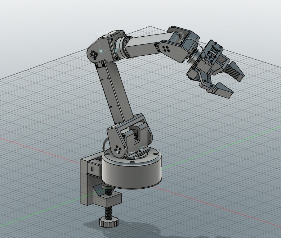
The goal of the project was a desk-scale robotic arm built from 3D-printed parts and hobby-grade actuators. I previously attempted Version 1, a four degree of freedom arm on MG90S hobby servos, and did not finish it. Those servos do not report position, so the controller commands a joint angle without confirming the joint reached it. Version 2 is a six degree of freedom design on serial-bus servos that report position at every joint, complete in CAD and not yet built.
Design Requirements
- Six joints and a gripperBase yaw, shoulder, elbow, forearm roll, wrist pitch, tool roll.
- Position feedbackEncoder position feedback at every joint on a single serial bus.
- Payload200 g payload held within rated servo torque across the working reach.
- MountingPrinted structure that clamps to a desk edge.
- AssemblyEvery fastener reachable with a straight driver at its assembly step.
Structure and Actuation
Top-down reach at table height.
Payload within every servo's rated torque out to 400 mm.
Upper arm and forearm lengths.
- ServosFeetech STS3250 and STS3215 serial-bus servos with magnetic encoders, daisy-chained on one bus. Two STS3250 servos drive the shoulder together and an STS3250 drives the elbow.
- SizingServos sized from a gravity-torque model: a 200 g payload is held within every servo's rated torque out to 400 mm.
- BearingsA 6810 thin-section bearing carries the base yaw joint and a 6806 bearing the forearm roll joint.
- Forearm hubThe forearm mounts on a separate hub, so the forearm roll servo's horn screws are driven straight down before the forearm is bolted on.
- Desk clampThe base clamps to a desk edge with a printed Tr16x4 trapezoidal clamp screw.
Gripper
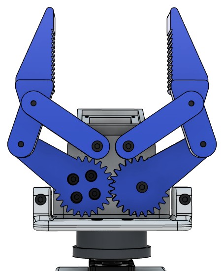
- Parallel linkageTwo meshed spur gears (module 1.25, 24 teeth), each driving a crank and a passive link that form a parallelogram, so the fingers stay parallel through a 62 mm opening.
- Grip facesStaircase grooves across both grip faces.
- Servo housingThe gripper servo sits in an enclosed housing and slides in from the back, behind a cover that carries its mounting screws and its wire exit. Minimum wall thickness is 3 mm.
- PalmPin bolts thread 8 mm into bosses behind the palm; side cheeks tie the palm to the front plate.
- CameraA pod on the back of the palm, on the servo side, holds the wrist camera.
Verification in CAD
Fasteners modelled at their holes and checked for seating and thread engagement.
Fastener lengths corrected by that check.
- Parametric modelModelled parametrically in Python (build123d) and rebuilt as a parametric Fusion 360 assembly with revolute joints and joint limits. A URDF is generated from the model.
- Fit checksEvery servo pocket and screw hole checked against the manufacturer STEP models: no overlaps, and every hole coaxial with the servo's hole.
- Cable routingWire windows sized from the servo's connector position, and printed hooks on the arm links.
- Assembly sequenceGenerated from the CAD: eight subassemblies built on the bench, then joined into the arm in 44 steps. Every insertion path is checked for intersection with the placed parts, and every screw head for a straight driver path, using exact geometry in Fusion 360.
Result
A complete six degree of freedom arm design in CAD, with servo sizing, fit checks against manufacturer models and a 44-step assembly sequence whose every insertion path and screw access is checked against the model.
Next Steps
I am building the arm now, working from the checked assembly sequence.
- Print and assemblePrinting the structural parts and building the eight subassemblies on the bench, then joining them into the arm in the 44 steps generated from the CAD.
- Bring-upWiring the servos onto the single serial bus, setting each joint's zero and limits against the CAD values, and driving the joints from the generated URDF.
- TrainingTeaching the arm tasks once it moves, with the wrist camera in the loop, and comparing what the built arm does against the model it was designed from.