Background
A connecting rod transmits force between the piston and the crankshaft and carries high cyclic compressive loads during combustion. The goal of the analysis was to find the stress at the piston pin bore and at the thinnest cross-section of the shank under a peak combustion load, and to check both against hand calculations.
2024 · SolidWorks
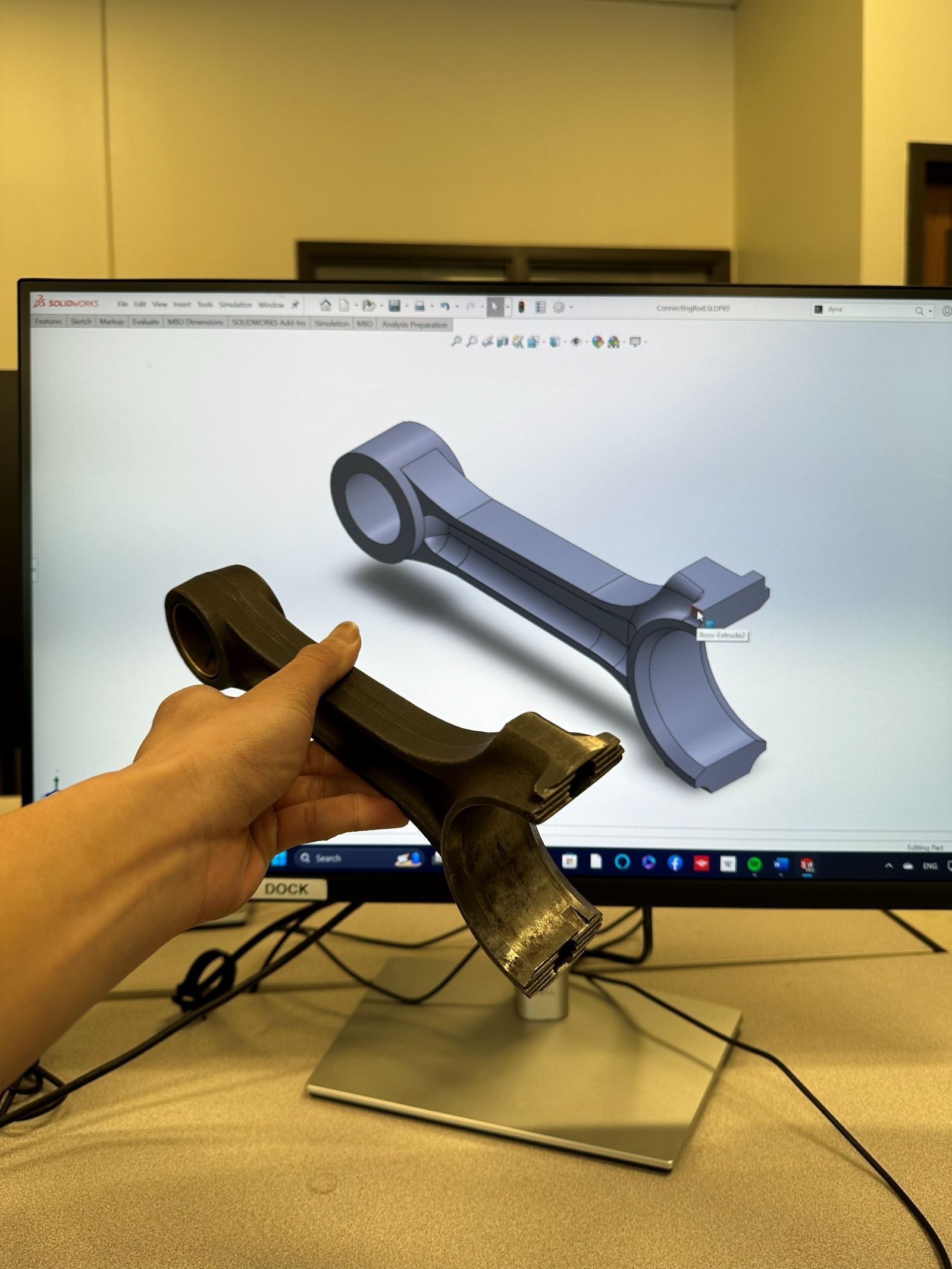
A physical piston and connecting rod measured with calipers, modelled in SolidWorks, and documented in drawings.
Spring 2026 · FEA course
Static structural analysis of a simplified connecting rod in ANSYS Mechanical.
Reverse Engineering
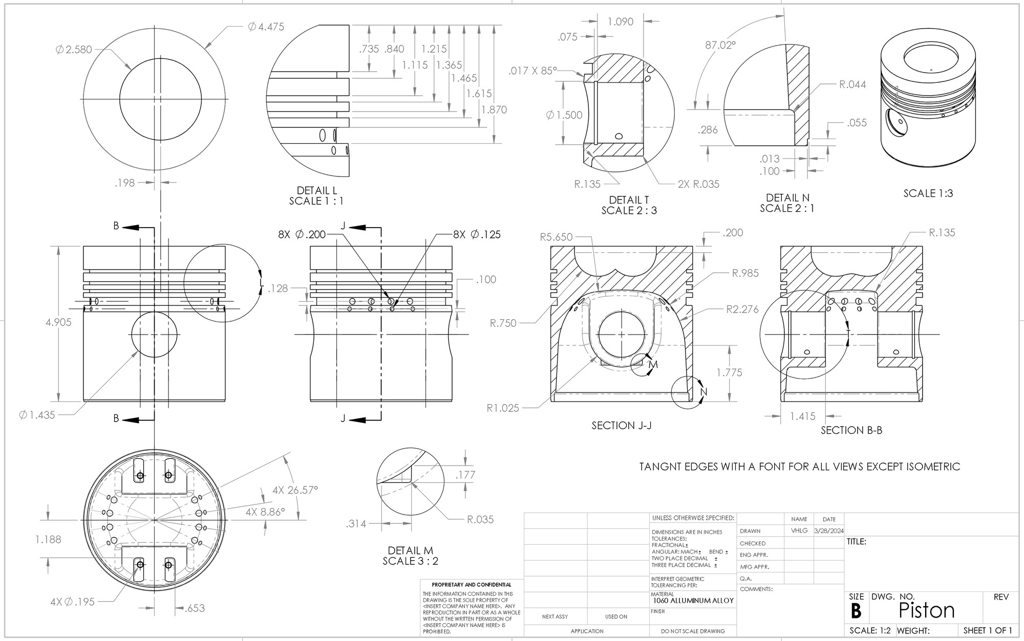
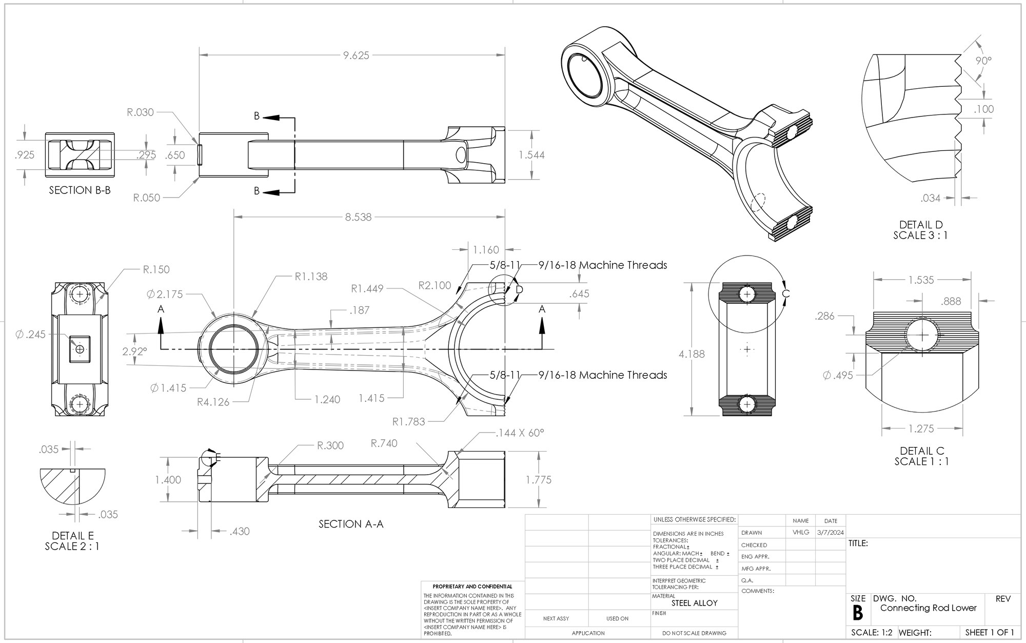
A physical piston and connecting rod were measured with calipers, modelled in SolidWorks, and documented in drawings with section and detail views: the piston in 1060 aluminum alloy, the connecting rod in steel alloy.
Model, Loads and Supports
- Geometry. Most connecting rods have an I-beam body whose cross-section changes along the length. The model uses a rectangular cross-section.
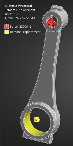
- Load. 25,000 N compressive force on the inner face of the piston pin bore, representing peak combustion loading.
- Support. Remote displacement at the big end bore, constraining translation and allowing rotation about the crank axis, to approximate the crankpin bearing.
Material · Structural steel
- Young's modulus
- 200 GPa
- Poisson's ratio
- 0.30
- Density
- 7850 kg/m³
- Yield strength
- 250 MPa
- Ultimate strength
- 460 MPa
Mesh and Convergence
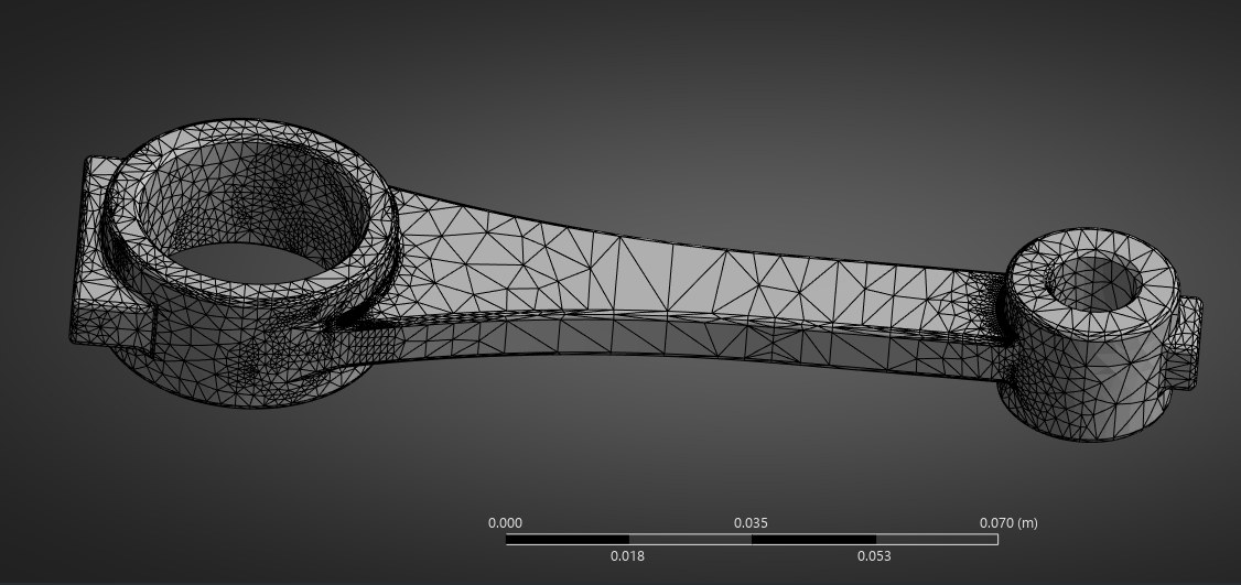
- Element type. Tet10 (quadratic 10-node tetrahedra), which conform to the curves and fillets of the rod.
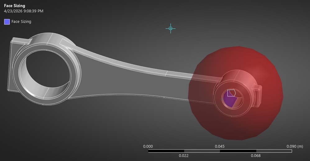
- Refinement. A sphere of influence around the piston pin bore to capture local stress concentrations.
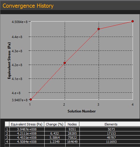
- Convergence. Equivalent stress changed 1.23% between the last two meshes while the element count more than doubled.
| Run | Global | Bore face | Elements | Stress | Change |
|---|---|---|---|---|---|
| 1 | 20 mm | 5 mm | 5,073 | 394.9 MPa | — |
| 2 | 10 mm | 4 mm | 17,153 | 421.1 MPa | 6.43% |
| 3 | 7 mm | 2 mm | 49,787 | 445.3 MPa | 5.59% |
| 4 | 5 mm | 1 mm | 111,693 | 450.8 MPa | 1.23% |
Results and Hand Calculation Check
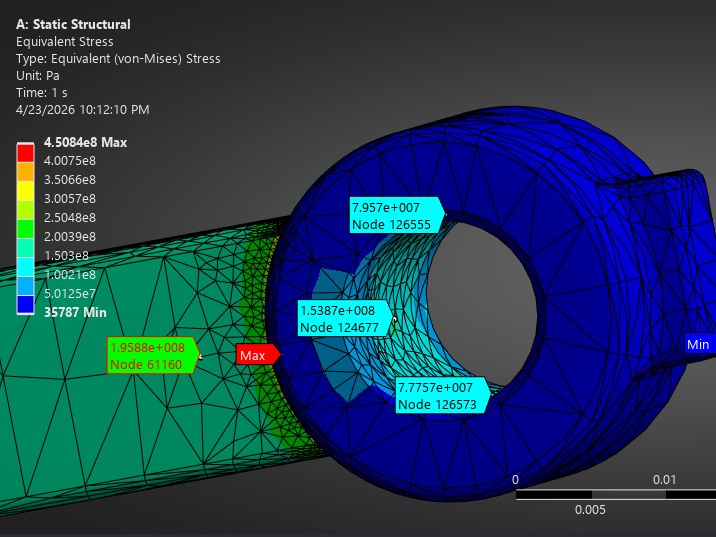
Stress was probed at the two regions of interest and compared with P/A estimates. Both probed values are below the 250 MPa yield strength, so the rod does not yield under the 25,000 N load.
Piston pin bore · bearing stress
25,000 N / (20 mm × 12.5 mm). FEA value is the average of three probes: 153.9, 79.6 and 77.8 MPa.
Thinnest shank section · axial stress
25,000 N / (8 mm × 16 mm), probed at the thinnest section of the shank.
Sources of Error
Support simplification
A cylindrical support was intended at the big end bearing. ANSYS recognized the bore as split geometry and would not accept it, so remote displacement was used, which deviates from the ideal constraint.
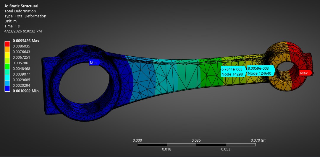
Deformation at the small end
Maximum deformation appears on the outer surface of the small end rather than the loaded inner face: the loaded bore compresses and the ring opens outward.
Fillet transitions
The shank-to-ring fillets and changing cross-sections are not captured by the uniform rectangular sections in the hand calculations. Refining the mesh in those zones improves accuracy.
Result
A converged static structural model of a connecting rod whose probed stresses matched hand calculations within 4%, with both values below yield under a 25,000 N combustion load.